rtos

Tuesday, September 28, 2021

Bootload Atmel MCU and make it Standalone using Arduino.

 What is bootloader ?

Its a small piece of code. The Arduino bootloader is run when the microcontroller is turned on(or when you press the reset button). This bootloader initially(for a very small time) waits for a new sketch on the serial port from the Arduino IDE, if it gets something, the new sketch is burned in to the flash memory and run or else it runs the sketch which was previously burned.

Why Bootloader ?

The bootloader exists because there is no standardized protocol for loading the first code, since it is chip dependent. Sometimes the code can be loaded through a serial port, a flash memory, or even a hard drive. It is bootloader function to locate it.

How to bootload new IC ?

If you have empty board to place new ic bootload will become very easy just follow below Circuit Diagrams

Arduino / Genuino BoardMOSIMISOSCKLevel
Uno or Duemilanove11 or ICSP-412 or ICSP-113 or ICSP-35V
Mega1280 or Mega256051 or ICSP-450 or ICSP-152 or ICSP-35V
LeonardoICSP-4ICSP-1ICSP-35V
DueICSP-4ICSP-1ICSP-33,3V
ZeroICSP-4ICSP-1ICSP-33,3V
10111 or ICSP-412 or ICSP-113 or ICSP-33,3V
MKR Family81093,3V

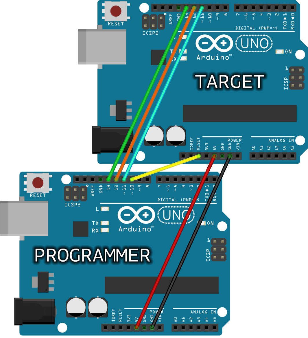
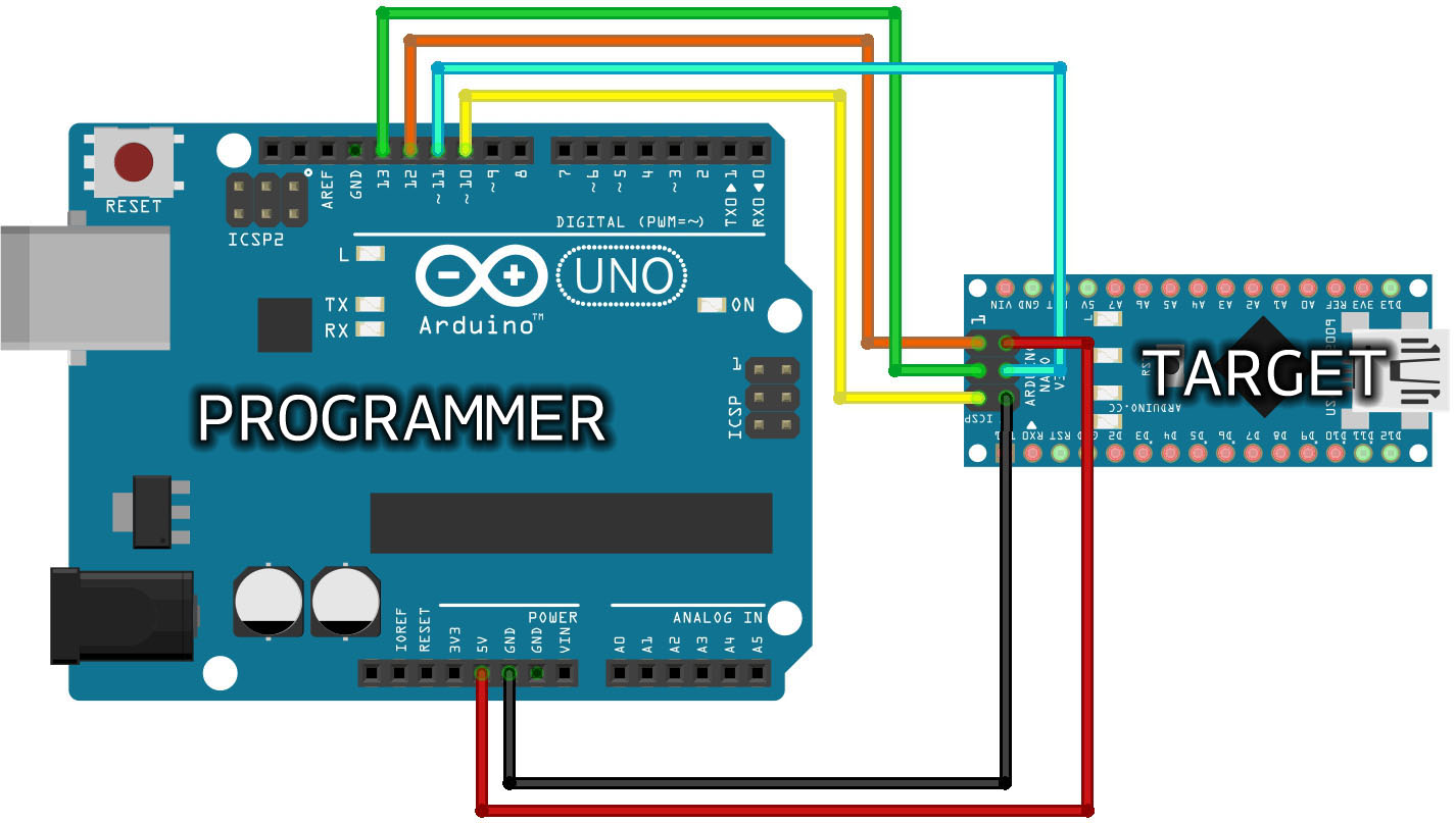
For Circuit Reference:

Note: Target board means the new IC you need to insert in old board to bootload it.

Bootload new Atmega328/Atmega8 using OLD Uno Board

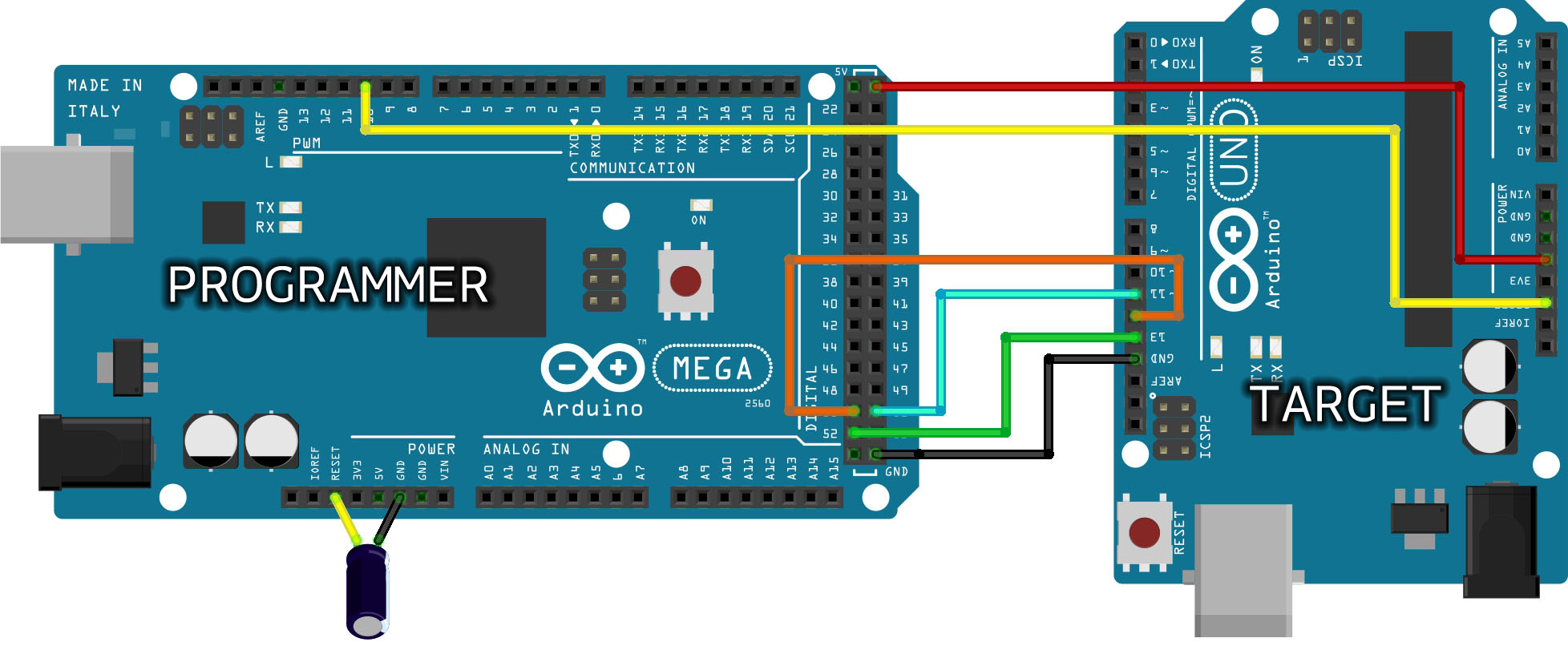
In last Circuit there is capacitor valued 0.10uF.

in arduino mega board you need to connect it. Electrolyte capacitor Positive to Reset and negative to Ground.

Whats Next ?

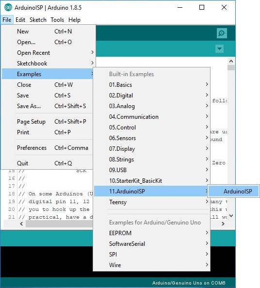
STEP 1: Open your Arduino IDE. In your menu, select 
File > Examples > 11.ArduinoISP > ArduinoISP to open up the Arduino as ISP sketch

Arduino as ISP Sketch

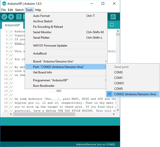
STEP 2: Select the COM port for your Arduino as ISP. The COM port may be different depending on how it enumerated on your computer.

Select COM Port

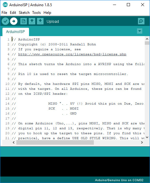
STEP 3: Upload the code to your Arduino to turn it into a AVRISP.

Upload Code

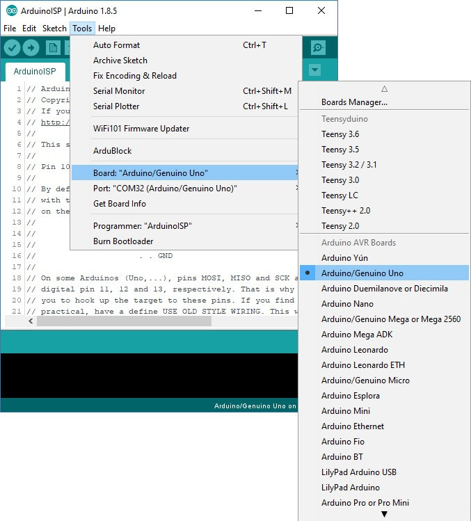
STEP 4: Burning a Bootloader to Your Target

Leave the Arduino as ISP (i.e. your programmer) connected to your computer. If you have not already, connect your target Arduino. Then select the your target Arduino under Tools > Board.

IF you are going to bootload atmega328 ic then select Board as UNO. If you are bootloading some other IC like Atmega8, you need to select that IC as board.

Board Selection for Target

Select the programmer that you are using under Tools > Programmer. In this case, our programmer is an Arduino as ISP so select Arduino as ISP. You will also need to select the COM port that the Arduino as ISP is connected to if you have not selected the COM port already.

Programmer

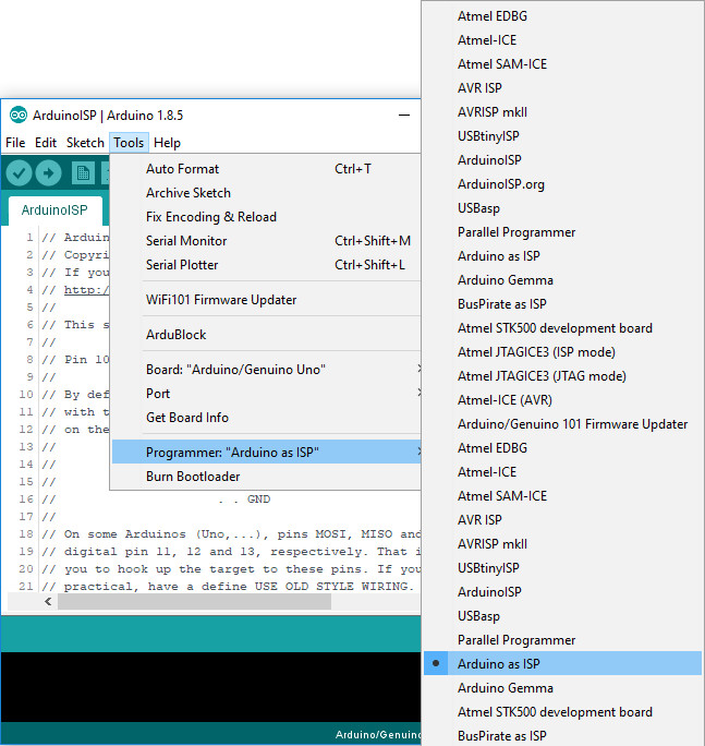
Heads up! You may encounter more than one selection for “Arduino as ISP” in the list of programmers. Either one will work. However, “ArduinoISP” will not work if it is selected.

Finally, select Burn Bootloader. This will take the board you selected in the Arduino IDE and look up the associated bootloader in the board.txt file. Then, it will find the bootloader in the Arduino IDE’s program folder (specifically “…\Arduino\hardware\arduino\avr\bootloaders“) and install it. This only works if the board is installed correctly in the IDE and you have the correct bootloader.
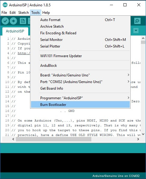
Burn Bootloader

Thats all !!!!

Any doubt ask below~!!!!

Calculate the Battery charging and discharging time.

 
What is battery ?
Batteries are a collection of one or more cells whose chemical reactions create a flow of electrons in a circuit. All batteries are made up of three basic components: an anode (the ‘-‘ side), a cathode (the ‘+’ side), and some kind of electrolyte (a substance that chemically reacts with the anode and cathode). for more information about battery visit Sparkfun official site
Understand battery terms
You can take any batteries it has some common parameters like voltage, current, temperature ratings, etc. let us look at the terms we see in batteries
Voltage
The battery voltage is mentioned on the battery body, normally it rated in V (volts) something like this >> 3.7V, 9V, 12V. It indicates that the battery can able to provide the voltage it stated on the label. For example, the 12v battery can able to supply 12V until it gets a discharge. 
Current
Current in the battery is given in Ah or mAh an ampere-hour (abbreviated Ah, or sometimes amp hour). let see this term by an example.
you have a battery and is rated as 12V and 1.3AH. here we can view two technical terms voltage and current. As we understand that the term voltage referred to as max voltage that the battery can able to supply until it gets a discharge. Now lets come to the point another term called current in Ah or mAh it can be called as amp-hour or milliamp-hour. we know that the current is the flow of electrons and hour is referred to the time. So your 1.3Ah battery can able to drive 1.3A load for one hour.
How to calculate charging time of the battery
Battery Charging
Charging a battery is a process of filling the electronics in side the battery and creating the chemical reaction that holds the potential of electronics and discharge it whenever needed to the circuit when we connect closed circuit.
we can charge the battery in several methods either by charging circuit just like a mobile phone charger or by using the dc power supply just like a battery to battery charging. or by other power sources like solar etc.
the main motive of charging the battery is to fill the electrons inside the battery in any way using DC power supply. okay, here we have a question what is the voltage and current rating for charging the battery?
as we already saw battery voltage is the voltage level where the battery charger should supply. no more than that or lesser than that voltage should supply to the battery. if the lesser voltage is applied then the battery will not get charged fully. if overvoltage is applied to it, battery plates may get damage and battery may lose its capacity and some unexpected things also may happen.
Battery charging current is the current rating battery should charge and charger should limit the current. how do we know battery charging current? simple, charging current should be 10% of the Ah rating of the battery.
Battery Charging Time and Battery Charging Current Formula for Batteries. (With Example of 120Ah Battery).
Below is a simple battery charging current and battery charging time formulas with a solved example of 120Ah lead acid battery
Here is the formula of charging time of a lead acid battery.
Charging time of battery = Battery Ah / Charging Current
T = Ah / A
Where,
T = Time hrs.
Ah = Ampere Hour rating of battery
A = Current in Amperes given by charger or charging circuit
Example:
Suppose for 120 Ah battery,
we calculate charging current for 120 Ah battery. As we know that charging current should be 10% of the Ah rating of battery.
Therefore,
Charging current for 120Ah Battery = 120 Ah x (10/100) = 12 Amperes.
But due to some losses, we may take 12-14 Amperes for batteries charging purpose instead of 12 Amp.
Suppose we took 13 Amp for charging purpose,
then,
Charging time for 120Ah battery = 120 / 13 = 9.23 Hrs.
But this was an ideal case…
Practically, it has been noted that 40% of losses occurs in case of battery charging.
Then 120 x (40 / 100) = 48 …..(120Ah x 40% of losses)
Therefore,  120 + 48 = 168 Ah ( 120 Ah + Losses)
Now Charging Time of battery = Ah / Charging Current
Putting the values;
168 / 13 = 12.92 or 13 Hrs ( in real case)
Therefore, an 120Ah battery would take 13 Hrs to fully charge in case of the required 13A charging current.
Normally in electronics practical and ideal will have great difference. it is because of the environment and the device properties with respect to age.
Battery Discharging time
We have seen the battery charging time and now we have a battery fully charged right ? lets talk about how long will be the battery can supply the power to the circuit ? to understand this concept we should know the concept of load current.
Load Current
What is Load ? An electrical load is an electrical component or portion of a circuit that consumes electric power. every components we use in electronics or electrical consumes power.
how do we know the Load current ?
Simple !! It is given in the device datasheet. say for example you can see any electrical appliances in the home it has a power rating in watt same as every motor, microcontroller, led, etc., has power ratings. and if you can’t understand let us make it too simple let us take LED and it normally rated 20mA so it is called the load current. The load current is the current needed to drive components. The component may be a Motor or Microcontroller or anything maybe. the current needed to drive the device is called load current.
Calculate Battery Discharge time
So we know what is Load current right? ok in system number of components going to be present and they are all going to consume power. so if you want to find the battery discharging time first calculate the entire circuit power consumption. get the datasheet of each component and note down the current rating of every component and finally add it you will get the load current.
another step to find the load current connect the ammeter in series to the circuit while it drives.
Image result for connect ammeter in series
In the above picture, we have bulb replace your circuit positive and negative end of bulb connection to find the total current drawn by the circuit
Okay we know the system load current then lets do the math now
Lets take an example that your circuit contain microcontroller which consume 500mA and you have dc motor that also consume 500mA then totally you have 1A load current. Assume that you use 5Ah Battery. formula for battery discharging time is
Battery Discharging time (in hours) = Battery capacity in AH / Load current or(current drop of the circuit)
Let’s apply it in the formula
Battery discharging time = 5Ah / 1A
5 Hours
If you use 5AH battery and 1A load your battery will supply the rated voltage up to 5 Hours.

This is ideal result in practical it may get vary.

How to Cut off power for HC-SR04 Ultrasonic Sensor using Transistor (Effective way of Switching)

 Here PN2222 Transistor BJT is working as a switch.


Use  Below Circuit to Switch the Ultrasonic Sensor.


Switching HC-SR04 Ultrasonic Sensor for Power Saving


Connection :

Use NPN PN2222 Transistor.

  1. Connect Base of the transistor with 1K resistor to digital output of the micro controller. 
    1. whenever you provide an output to the Base HC-SR04 will get power. if base has no input supply, HC-SR04 will be on off condition which here referred as a power saving mode.
  2. Connect Collector of the transistor to ultrasonic sensor GND
  3. Connect Emitter to GND of the battery or Controller GND

Any Doubts comments below…..

How to clone Raspberry Pi Compute Model 4 and Flash it to other Raspberry Pi

     If you are working with some projects where you used Raspberry Pi, You may done lot of code and configuration. When it goas to production and You have hundreds of Boards you can't make changes in every modules. So here there is a solution for that. You can clone the entire OS, Mostly all your files and configuration are unchanged. This made work easier when you need exact setup for multiple devices. 

This is for Compute Module. You can follow for Normal Raspberry Pi module but skip step 1 if you do so.

Step 1 : Install rpiboot

  • rpiboot used to flash compute module eMMC.  If you already flash OS to Computer module then you probably have installed it.  If not Download it from this link and do normal installation in Windows. 
  • Start rpiboot after connecting Raspberry Pi module to the PC using MicroB Cable. Power up using another Micro B cable USB which you connected to PC will not provide power to the Module.
  • Once you opened rpiboot it after few seconds you can able to see the Compute module Disk in the Explorer Device and Drivers Section. It will looks like you have inserted an external SD card or Pendrive. If you can see this you just passed the first step. 

Step 2 :  Install Win32DiskImarger 

  • Win32DiskImager is used to Read OS Image and to Write Image file in a SD Card or Compute Module. 
  • Download and Install from here

Step 3 : Read Compute Module OS and save clone in a folder

  • Open Win32DiskImager
  • Select Your compute Module on Device Section 
  • Click Image File Browse and Give any name and save it
  • Click Read Button from Bottom, It will clone the OS and save it in the name you have given and path you have selected. It will take some time. 
  • Once its done you can see the Cloned OS in the path with the name you have given.

Step 4 : Flashing Cloned OS to Another Computer Module.

  • Complete Step 1 to enable the visibility of new compute module in Explorer.
  • Open Win32DiskImager
  • Select Cloned Image in image file section from Browse option.
  • Select Compute module in Device Section. 
    • If you have already Flashed OS and if you are not worry about erasing it, I suggest you to format it and Go to Disk Management > Delete All main and Sub Partition related to Pi Module. Make new Partition.
  • After Completing above steps make sure you have seen only one Partition and Click Write Option.
  • It will take few minutes and chill with some music.....
   Your Cloned OS is ready now. Enjoy, If you have any Queries please feel free to ask


Guide to use ProtocolBuffers (nanopb) in IoT Devices.

 What is Protocol Buffer?      I hope the reader is familiar with JSON format. It's a widely used data format for communicating between...