rtos

Thursday, October 13, 2022

Guide to use ProtocolBuffers (nanopb) in IoT Devices.

 What is Protocol Buffer?

    I hope the reader is familiar with JSON format. It's a widely used data format for communicating between two different programs. Many mobiles and web applications use JSON for data exchange. Because it's easy to use and human-readable. Many IoT applications are also using JSON for data exchange. But there is a good tool that can help to cut down the data packets size sends over the internet.  It's called Protocol Buffers. 

Nanopb is an ANSI-C library for encoding and decoding messages in Google's Protocol Buffers format with minimal requirements for RAM and code space. It is primarily suitable for 32-bit microcontrollers.

Protocol buffers, usually referred to as Protobuf, is a protocol developed by Google to allow serialization and deserialization of structured data. Google developed it with the goal to provide a better way, compared to XML and JSON, to make systems communicate. So they focused on making it simpler, smaller, faster, and more maintainable than XML and JSON. 

Microcontrollers use Protocol Buffers in IoT devices. It decreases the packet size, and reduces delivery time. 

How do Protocol Buffers works?

The developer writes the Data structure schema in a .proto file. Then that file will be passed to the python script. Python script will generate a C header and C source file for encoding and decoding the data structure just now the developer described in the .proto file.  User needs to use these C files inside their project directory to encode or decode. for more information refer to https://github.com/nanopb/nanopb

Process Overview

Image:     .proto file to c data structure converter

How to Install protocol buffers and dependencies?

This example is focused Linux system

     Below mentioned are the Dependencies:

  • Python
  • Python Protobuf-Library
  • Protoc
If python is not installed on the computer, Install it manually, and then it's easy to install other dependencies. 
  • Once the Python is installed then type the below command 
pip install --upgrade protobuf grpcio-tools

If it's successfully installed then good to go.  

  • Clone the nanopb GitHub directory

git clone https://github.com/nanopb/nanopb.git

How to use protocol buffers?

  • Once the installation is completed create a new directory inside nanopb.  I prefer location nanopb/examples.

            ex: directory named "sample" is created and its path looks like -> nanopb/examples/sample.

  • Create a file name sample.proto
    • "sample"  is the name taken for example but you can name it related to your project.

What is a <sample.proto> file is all about?

If you observe the basic C structure, It needs definition before we can use it in the main program. Just like that, .proto is a file where the developer writes the data structure. It almost looks like C but with a little different syntax. 

Ex:

Step 1: Creating a structure.

Type this in the sample.proto file 

syntax = "proto3";
message Example {
    int32 lucky_number = 1;
}

Here,

        syntax="proto3"

This tells the Protocol Buffer compiler to use protocol version 3. If it's not specified then by default it takes proto2 version. 

    message Example

 "message" is the keyword used in the protocol buffer to create a structured schema followed by the user-defined message name. Here "Example" is the user-defined name. 

    int32 lucky_number=1

just like uint32_t in C, we can use int32 to create a 32-bit integer variable in our code to store some sensor data or any other use desired values. Number 1 is used to identify the fields by Protobuf and it should be unique for a structure. There are number of data types supported by Protobuf. 

click here to check different types of Data Types supported in Protobuf 

https://jpa.kapsi.fi/nanopb/docs/concepts.html#data-types

Step 2: Generating C files.

Type the below command to generate C files in the terminal under the examples/sample directory.

python ../../generator/nanopb_generator.py sample.proto

It will generate 2 files sample.ph.c and sample.ph.h.
You can open sample.ph.h file and check for the C structure. It will be something like the one below. 

/* Struct definitions */
typedef struct _Example { 
    int32_t lucky_number;
} Example;

This is exactly the C structure.

Step 2: Adding Protobuf to your project.

To Use the protobuf in your project you need the below-mentioned files 

pb_encode.h/c

pb_decode.h/c

pb_common.h/c

pb.h

sample.ph.h/c  <message> same as the name of the .proto file

Physically Add all these files into your project directory or include a path to your project build system. message.ph.h/c files are generated from the previous command and the remaining files can be found on the root directory of the protobuf GitHub directory. 

Include these files in the header of the C file where messages needs to to encoded or decoded.

#include "sample.ph.h"

#include "pb_encode.h"

#include "pb_decode.h"

If you use only encoding on your code then include only pb_encode.h file.

Example of Encoding and Decoding:

Once the protobuf generates the message.ph.h/c files copy and paste all the file names mentioned in <adding protobuf to your example> section in the root directory or include the path to your build system.

Since many embedded systems are platform dependent we are going to check encoding and decoding in basic C which is same in many C based embedded developments. 

Create a c file named main.c in the root directory where all of your files are pasted. You can used those files stand alone in any other directory and there is no dependency for that since it all independent C file. But all files should be present in the same directory or path should be included in build system. once the files are included the project contains below files. 

pb_encode.h/c

pb_decode.h/c

pb_common.h/c

pb.h

sample.ph.h/c

main.c :( C file to implement Encode Decode logics)

#include <stdio.h>
#include "pb_encode.h"
#include "pb_decode.h"
#include "sample.pb.h"
int main()
{
/* This is the buffer where we will store our message. */
uint8_t buffer[128];
size_t message_length;
bool status;
/* Encode our message */
{
/* Allocate space on the stack to store the message data.
*
* Nanopb generates struct definitions for all the messages.
* - check out the contents of sample.pb.h!
* It is a good idea to always initialize your structures
* so that you do not have garbage data from RAM in there.
*/
SampleMessage message = SampleMessage_init_zero;
/* Create a stream that will write to our buffer. */
pb_ostream_t stream = pb_ostream_from_buffer(buffer, sizeof(buffer));
/* Fill in the lucky number */
message.lucky_number = 13;
/* Now we are ready to encode the message! */
status = pb_encode(&stream, SampleMessage_fields, &message);
message_length = stream.bytes_written;
/* Then just check for any errors.. */
if (!status)
{
printf("Encoding failed: %s\n", PB_GET_ERROR(&stream));
return 1;
}
}
/* Now we could transmit the message over network, store it in a file or
* wrap it to a pigeon's leg.
*/
/* But because we are lazy, we will just decode it immediately. */
{
/* Allocate space for the decoded message. */
SampleMessage message = SampleMessage_init_zero;
/* Create a stream that reads from the buffer. */
pb_istream_t stream = pb_istream_from_buffer(buffer, message_length);
/* Now we are ready to decode the message. */
status = pb_decode(&stream, SampleMessage_fields, &message);
/* Check for errors... */
if (!status)
{
printf("Decoding failed: %s\n", PB_GET_ERROR(&stream));
return 1;
}
/* Print the data contained in the message. */
printf("Your lucky number was %d!\n", (int)message.lucky_number);
}
return 0;
}
view raw main.c hosted with ❤ by GitHub

Copy and pase the above code in main.c file. Comments sections in the code explains code very well. 

Once the files are ready now lets compile the code and run.

Run in the files workspace directory :

gcc */c -o main

this will compile and generate executable file. 

To run the code type below command 

./main

output will be 

Your lucky number was 13!

Tuesday, October 11, 2022

How to use Zephyr ADC with NRF9160DK?

Technical Terms:

1. What is meant by 8-channel ADC?

        8 Channel ADC in Microcontroller means 

    • 8 pins of microcontrollers can be used to receive that many analog signals which can in turn be digitized.
    • However and usually there is one ADC in the microcontroller. NRF9160 ADC
    • The inputs at the pin are selected and connected to ADC via. Analog Multiplexer (part of microcontroller or ADC) one at a time
    • ADC delivers the digital code of the analog signal at the channel or pin number, which is connected to its input at a given instance.
Analog-to-digital converters (ADCs) need a reference voltage (VREF) input in order to operate properly. ADCs convert analog inputs that can vary from zero volts up to a maximum voltage level which is called the reference voltage.
    When we use the internal reference 0.6V as the ADC reference voltage, we cannot pass a voltage of more than 0.6V to ADC pins directly. If we do so the ADC output will be undesired(sometimes it will show 1024 in if it's 10 bit and sometimes it may be reduced to lower just like variable overflow). To increase/decrease the input range above the reference voltage Gain is used.  

Gain is nothing but performing multiplication or division with the actual input voltage before passing it to the ADC converter. Check this image of ADC

You can see the Gain block present between the Input voltage and the ADC circuit. We can configure this Gain to which number to be multiplied or to be divided from the Input voltage in order to provide proper value to the ADC that matches the Reference voltage. 

Example: 

Assume we chose the Internal reference voltage which is 0.6 Volt.  According to theory, we cannot pass voltage above 0.6V to ADC Channels. Let's say you want to read the AA battery voltage which is 3.6 Max Voltage (for simplicity without a voltage divider). You need to use Gain in order to make ADC work in the range of up to 3.6V. You can select 1/6 gain. By doing so it will divide the incoming voltage by 6 and pass it to ADC. 

Assume you passed an input voltage is 3.6V to ADC Pin, and you selected gain as 1/6. then the Gain part in the circuit divides the 3.6V by 0.6V. output it 0.6V. Which is exactly not greater than the internal reference voltage. 

 Zephyr ADC Supports the below gain configurations.


/** @brief ADC channel gain factors. */
enum adc_gain {
ADC_GAIN_1_6, /**< x 1/6. */
ADC_GAIN_1_5, /**< x 1/5. */
ADC_GAIN_1_4, /**< x 1/4. */
ADC_GAIN_1_3, /**< x 1/3. */
ADC_GAIN_1_2, /**< x 1/2. */
ADC_GAIN_2_3, /**< x 2/3. */
ADC_GAIN_1, /**< x 1. */
ADC_GAIN_2, /**< x 2. */
ADC_GAIN_3, /**< x 3. */
ADC_GAIN_4, /**< x 4. */
ADC_GAIN_6, /**< x 6. */
ADC_GAIN_8, /**< x 8. */
ADC_GAIN_12, /**< x 12. */
ADC_GAIN_16, /**< x 16. */
ADC_GAIN_24, /**< x 24. */
ADC_GAIN_32, /**< x 32. */
ADC_GAIN_64, /**< x 64. */
ADC_GAIN_128, /**< x 128. */
};


If you select 1/6 as Gain then 
Input range = (0.6 V)/(1/6) = 3.6 V
You can pass up to 3.6V and the gain will divide by 1.6 and pass it to ADC


If you select 2 as Gain then 
Input range = (0.6 V)/(2) = 0.3 V

Convert the raw value to Volts

  •     Remember the Gain value Input range? We are going to use that now. 
Actual_Voltage = input_raw_value * (input_volt_range / resolution)
input_raw_value: Value read from adc_read(adc_dev, &sequence);function
input_volt_range: maximum input voltage range ex: if the gain is 1/6 then the max value is 0.6/(1/6) = 3.6.  here 0.6 is an internal reference voltage and 1/6 is the gain.
resolution10-bit ADC max value. 

Find the code in the Git repo

 https://github.com/manudevappa/zephyr_adc_sample

Wednesday, October 20, 2021

Basic Thread creation on Zephyr RTOS | Embeddedsea

Basic Thread creation on Zephyr RTOS | Embeddedsea

If you are a beginner to Zephyr and RTOS, This blog is for you. I'm gonna show you basics of how to create thread in Zephyr and show you basics of threads and working.

If you already working with Arduino or PIC micro controller you are working in Super Loop Style.

Round Robin is so easy to implement because it is a natural way of writing software. Developers simply add new code to the super loop and a task is now added. There is no need to create dynamic and memory expensive objects. Just add code!

It runs from to top to bottom by executing the task one by one. If you need any emergency works to be done it can be done by Interrupts. 

When some task is waiting for sometime other task also delayed due to the flow. It's not good right ?


Here is the working flow of RTOS.

When it comes to RTOS one of the the main advantage is Multi Threading. It's a ability to do more than one task at a time. 

For example: 

If you write thread with individual Infinite while loop, It will execute parallel. 


Refer above image, Each task has its own while loop and it will run Interdependently. If you want to pass values between tasks you may need to implement Queues, Mutex, Semaphore which can be discussed in future Blogs. Now we just look on how to run 3 task individually.

Note: Even it looks like parallel execution, It wont happens like that in single core CPU. It will allocate each task a period of time ex: 1 ms. for every period tasks will get switched from execution to read state and from ready state to execution. Scheduler will save running task  current variables and registers before switching to other task. when it move the previous task from ready state to run state it will retrieve the old variables data and allow it to Resume the executions.


Talk is cheap show me the code - Linus Torvalds.

Shall we jump into coding part ?? 


Here is the simple code to Run 3 task

Get full Code on Click here

/*
 * 
 * Author: Manu Devappa | manudevappsa@gmail.com
 * 
 * Implementation of MultiThread in Zephyr RTOS 
 * 
 */

#include <zephyr.h>
#include <device.h>
#include <drivers/gpio.h>
#include <sys/printk.h>
#include <sys/__assert.h>
#include <string.h>

/* size of stack area used by each thread */
#define STACKSIZE 1024


/* Thread 1*/
void thread1(void)
{
	while(1){
		// place any other code to run Here
		printk("1\n");
		k_msleep(100);
	}
}

/* Thread 2*/
void thread2(void)
{
	while(1){
		// place any other code to run Here
		printk("2\n");
		k_msleep(200);
	}
}

/* Thread 3*/
void thread3(void)
{
	while (1) {
		// place any other code to run Here
		printk("3\n");
		k_msleep(300);
	}
}


K_THREAD_DEFINE(blink0_id, STACKSIZE, thread1, NULL, NULL, NULL,
		7, 0, 0);
K_THREAD_DEFINE(blink1_id, STACKSIZE, thread2, NULL, NULL, NULL,
		7, 0, 0);
K_THREAD_DEFINE(uart_out_id, STACKSIZE, thread3, NULL, NULL, NULL,
		7, 0, 0);
Explanation: 

K_THREAD_DEFINE(namestack_sizeentryp1p2p3priooptionsdelay)

The ID of the thread can be accessed using:

Parameters
  • name – Name of the thread.

  • stack_size – Stack size in bytes.

  • entry – Thread entry function.

  • p1 – 1st entry point parameter.

  • p2 – 2nd entry point parameter.

  • p3 – 3rd entry point parameter.

  • prio – Thread priority.

  • options – Thread options.

  • delay – Scheduling delay (in milliseconds), zero for no delay.

    
    I tested Code with NRF9160dk_nrf9160 board. You can check with other boards it will work.

You can observe in Above code there is no main() function, We call thread at Compile time using MACRO. 

Build using


west build -p auto -b <yourboardname>

Flash using Jlink Installed in your system

west flash 


Tuesday, September 28, 2021

Bootload Atmel MCU and make it Standalone using Arduino.

 What is bootloader ?

Its a small piece of code. The Arduino bootloader is run when the microcontroller is turned on(or when you press the reset button). This bootloader initially(for a very small time) waits for a new sketch on the serial port from the Arduino IDE, if it gets something, the new sketch is burned in to the flash memory and run or else it runs the sketch which was previously burned.

Why Bootloader ?

The bootloader exists because there is no standardized protocol for loading the first code, since it is chip dependent. Sometimes the code can be loaded through a serial port, a flash memory, or even a hard drive. It is bootloader function to locate it.

How to bootload new IC ?

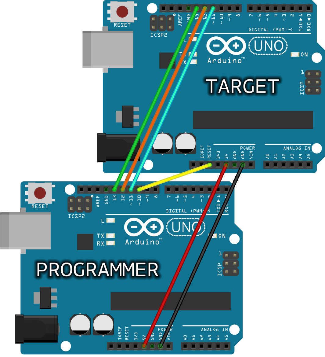
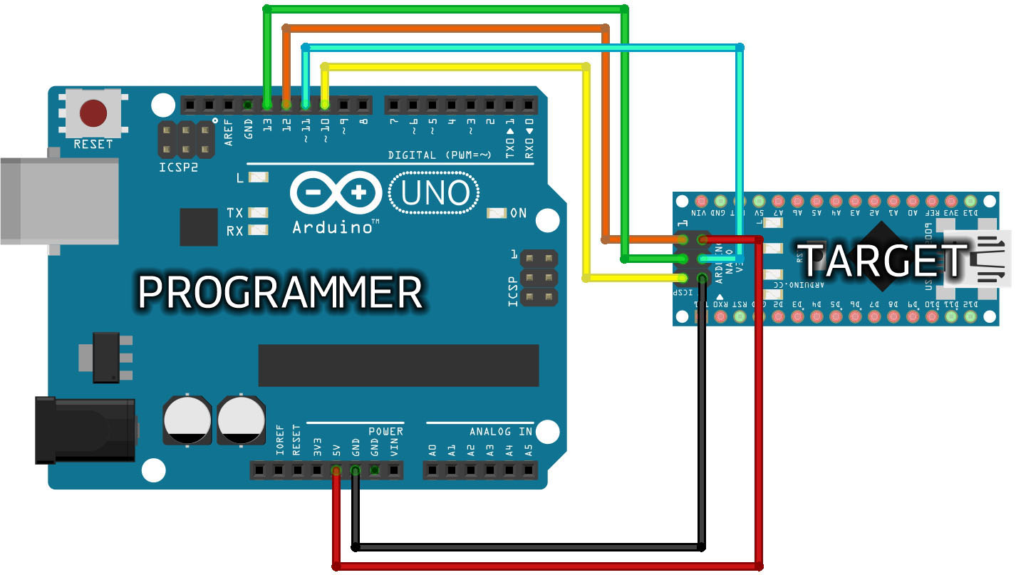
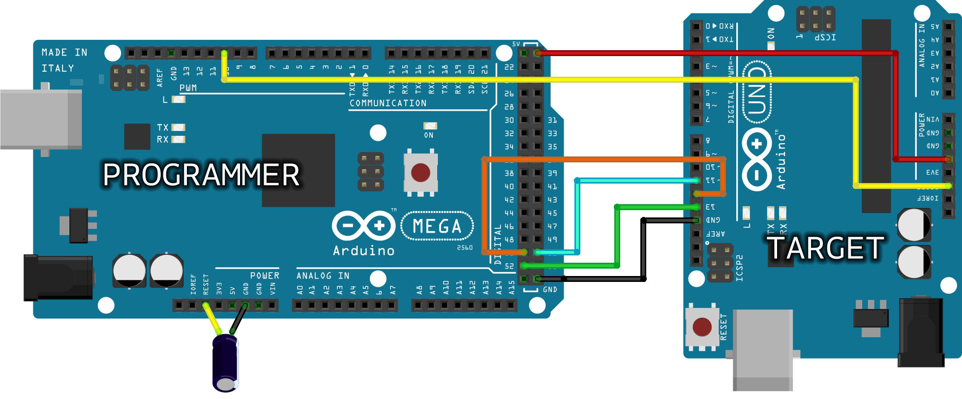
If you have empty board to place new ic bootload will become very easy just follow below Circuit Diagrams

Arduino / Genuino BoardMOSIMISOSCKLevel
Uno or Duemilanove11 or ICSP-412 or ICSP-113 or ICSP-35V
Mega1280 or Mega256051 or ICSP-450 or ICSP-152 or ICSP-35V
LeonardoICSP-4ICSP-1ICSP-35V
DueICSP-4ICSP-1ICSP-33,3V
ZeroICSP-4ICSP-1ICSP-33,3V
10111 or ICSP-412 or ICSP-113 or ICSP-33,3V
MKR Family81093,3V

For Circuit Reference:

Note: Target board means the new IC you need to insert in old board to bootload it.

Bootload new Atmega328/Atmega8 using OLD Uno Board

In last Circuit there is capacitor valued 0.10uF.

in arduino mega board you need to connect it. Electrolyte capacitor Positive to Reset and negative to Ground.

Whats Next ?

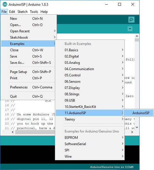
STEP 1: Open your Arduino IDE. In your menu, select 
File > Examples > 11.ArduinoISP > ArduinoISP to open up the Arduino as ISP sketch

Arduino as ISP Sketch

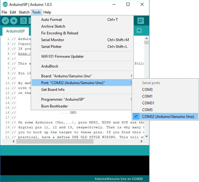
STEP 2: Select the COM port for your Arduino as ISP. The COM port may be different depending on how it enumerated on your computer.

Select COM Port

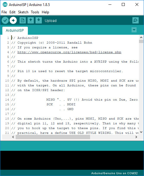
STEP 3: Upload the code to your Arduino to turn it into a AVRISP.

Upload Code

STEP 4: Burning a Bootloader to Your Target

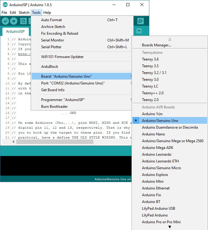
Leave the Arduino as ISP (i.e. your programmer) connected to your computer. If you have not already, connect your target Arduino. Then select the your target Arduino under Tools > Board.

IF you are going to bootload atmega328 ic then select Board as UNO. If you are bootloading some other IC like Atmega8, you need to select that IC as board.

Board Selection for Target

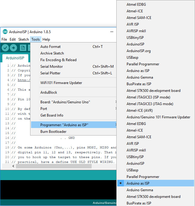
Select the programmer that you are using under Tools > Programmer. In this case, our programmer is an Arduino as ISP so select Arduino as ISP. You will also need to select the COM port that the Arduino as ISP is connected to if you have not selected the COM port already.

Programmer

Heads up! You may encounter more than one selection for “Arduino as ISP” in the list of programmers. Either one will work. However, “ArduinoISP” will not work if it is selected.

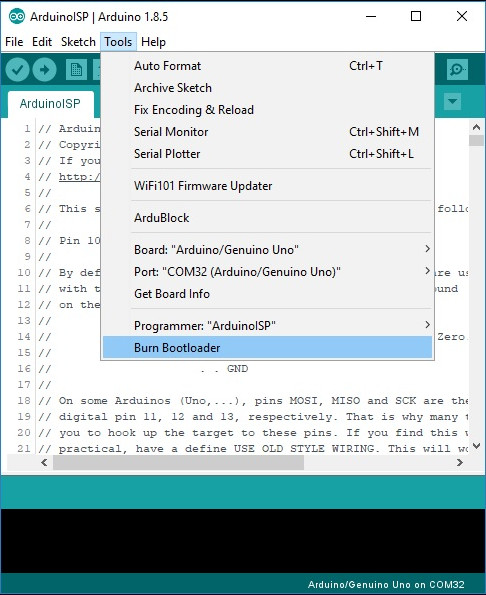
Finally, select Burn Bootloader. This will take the board you selected in the Arduino IDE and look up the associated bootloader in the board.txt file. Then, it will find the bootloader in the Arduino IDE’s program folder (specifically “…\Arduino\hardware\arduino\avr\bootloaders“) and install it. This only works if the board is installed correctly in the IDE and you have the correct bootloader.

Burn Bootloader

Thats all !!!!

Any doubt ask below~!!!!

Calculate the Battery charging and discharging time.

 
What is battery ?
Batteries are a collection of one or more cells whose chemical reactions create a flow of electrons in a circuit. All batteries are made up of three basic components: an anode (the ‘-‘ side), a cathode (the ‘+’ side), and some kind of electrolyte (a substance that chemically reacts with the anode and cathode). for more information about battery visit Sparkfun official site
Understand battery terms
You can take any batteries it has some common parameters like voltage, current, temperature ratings, etc. let us look at the terms we see in batteries
Voltage
The battery voltage is mentioned on the battery body, normally it rated in V (volts) something like this >> 3.7V, 9V, 12V. It indicates that the battery can able to provide the voltage it stated on the label. For example, the 12v battery can able to supply 12V until it gets a discharge. 
Current
Current in the battery is given in Ah or mAh an ampere-hour (abbreviated Ah, or sometimes amp hour). let see this term by an example.
you have a battery and is rated as 12V and 1.3AH. here we can view two technical terms voltage and current. As we understand that the term voltage referred to as max voltage that the battery can able to supply until it gets a discharge. Now lets come to the point another term called current in Ah or mAh it can be called as amp-hour or milliamp-hour. we know that the current is the flow of electrons and hour is referred to the time. So your 1.3Ah battery can able to drive 1.3A load for one hour.
How to calculate charging time of the battery
Battery Charging
Charging a battery is a process of filling the electronics in side the battery and creating the chemical reaction that holds the potential of electronics and discharge it whenever needed to the circuit when we connect closed circuit.
we can charge the battery in several methods either by charging circuit just like a mobile phone charger or by using the dc power supply just like a battery to battery charging. or by other power sources like solar etc.
the main motive of charging the battery is to fill the electrons inside the battery in any way using DC power supply. okay, here we have a question what is the voltage and current rating for charging the battery?
as we already saw battery voltage is the voltage level where the battery charger should supply. no more than that or lesser than that voltage should supply to the battery. if the lesser voltage is applied then the battery will not get charged fully. if overvoltage is applied to it, battery plates may get damage and battery may lose its capacity and some unexpected things also may happen.
Battery charging current is the current rating battery should charge and charger should limit the current. how do we know battery charging current? simple, charging current should be 10% of the Ah rating of the battery.
Battery Charging Time and Battery Charging Current Formula for Batteries. (With Example of 120Ah Battery).
Below is a simple battery charging current and battery charging time formulas with a solved example of 120Ah lead acid battery
Here is the formula of charging time of a lead acid battery.
Charging time of battery = Battery Ah / Charging Current
T = Ah / A
Where,
T = Time hrs.
Ah = Ampere Hour rating of battery
A = Current in Amperes given by charger or charging circuit
Example:
Suppose for 120 Ah battery,
we calculate charging current for 120 Ah battery. As we know that charging current should be 10% of the Ah rating of battery.
Therefore,
Charging current for 120Ah Battery = 120 Ah x (10/100) = 12 Amperes.
But due to some losses, we may take 12-14 Amperes for batteries charging purpose instead of 12 Amp.
Suppose we took 13 Amp for charging purpose,
then,
Charging time for 120Ah battery = 120 / 13 = 9.23 Hrs.
But this was an ideal case…
Practically, it has been noted that 40% of losses occurs in case of battery charging.
Then 120 x (40 / 100) = 48 …..(120Ah x 40% of losses)
Therefore,  120 + 48 = 168 Ah ( 120 Ah + Losses)
Now Charging Time of battery = Ah / Charging Current
Putting the values;
168 / 13 = 12.92 or 13 Hrs ( in real case)
Therefore, an 120Ah battery would take 13 Hrs to fully charge in case of the required 13A charging current.
Normally in electronics practical and ideal will have great difference. it is because of the environment and the device properties with respect to age.
Battery Discharging time
We have seen the battery charging time and now we have a battery fully charged right ? lets talk about how long will be the battery can supply the power to the circuit ? to understand this concept we should know the concept of load current.
Load Current
What is Load ? An electrical load is an electrical component or portion of a circuit that consumes electric power. every components we use in electronics or electrical consumes power.
how do we know the Load current ?
Simple !! It is given in the device datasheet. say for example you can see any electrical appliances in the home it has a power rating in watt same as every motor, microcontroller, led, etc., has power ratings. and if you can’t understand let us make it too simple let us take LED and it normally rated 20mA so it is called the load current. The load current is the current needed to drive components. The component may be a Motor or Microcontroller or anything maybe. the current needed to drive the device is called load current.
Calculate Battery Discharge time
So we know what is Load current right? ok in system number of components going to be present and they are all going to consume power. so if you want to find the battery discharging time first calculate the entire circuit power consumption. get the datasheet of each component and note down the current rating of every component and finally add it you will get the load current.
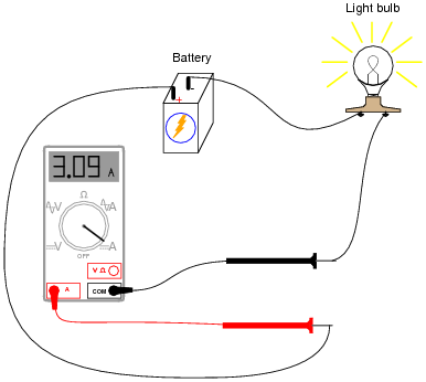
another step to find the load current connect the ammeter in series to the circuit while it drives.
Image result for connect ammeter in series
In the above picture, we have bulb replace your circuit positive and negative end of bulb connection to find the total current drawn by the circuit
Okay we know the system load current then lets do the math now
Lets take an example that your circuit contain microcontroller which consume 500mA and you have dc motor that also consume 500mA then totally you have 1A load current. Assume that you use 5Ah Battery. formula for battery discharging time is
Battery Discharging time (in hours) = Battery capacity in AH / Load current or(current drop of the circuit)
Let’s apply it in the formula
Battery discharging time = 5Ah / 1A
5 Hours
If you use 5AH battery and 1A load your battery will supply the rated voltage up to 5 Hours.

This is ideal result in practical it may get vary.

Guide to use ProtocolBuffers (nanopb) in IoT Devices.

 What is Protocol Buffer?      I hope the reader is familiar with JSON format. It's a widely used data format for communicating between...